Adventures in 3D printing PVC - Part 2
08 Apr 2017Testing the concept
Why? To investigate the behaviour of the PVC when extruded through a conventional 3D printing extruder, as well as to gain an insight into the pressures and temperatures required to process the material in this manner.
Experimental Setup
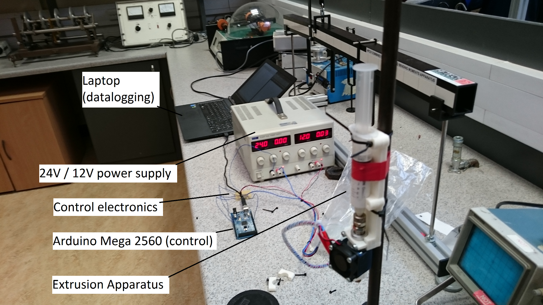
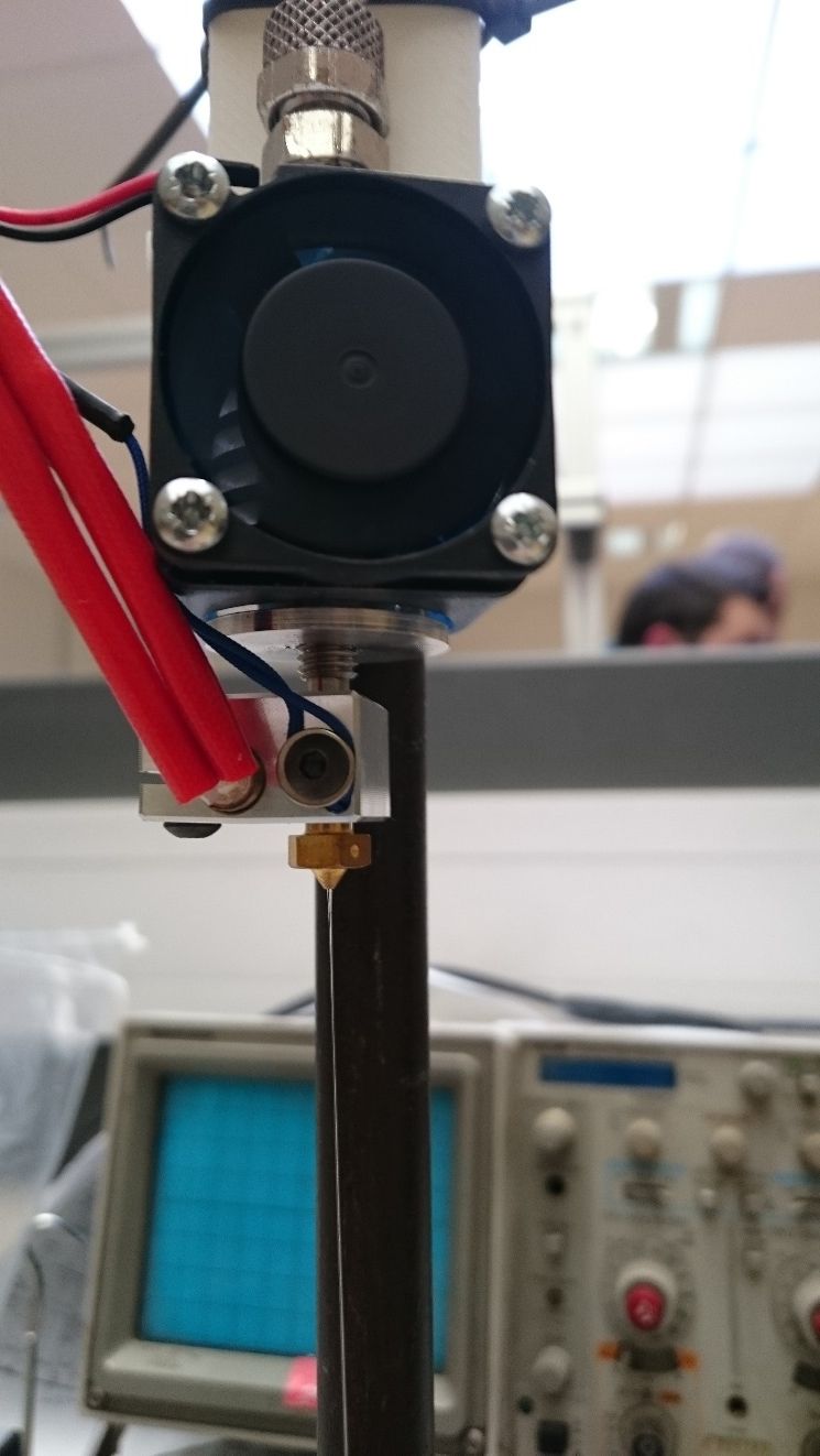
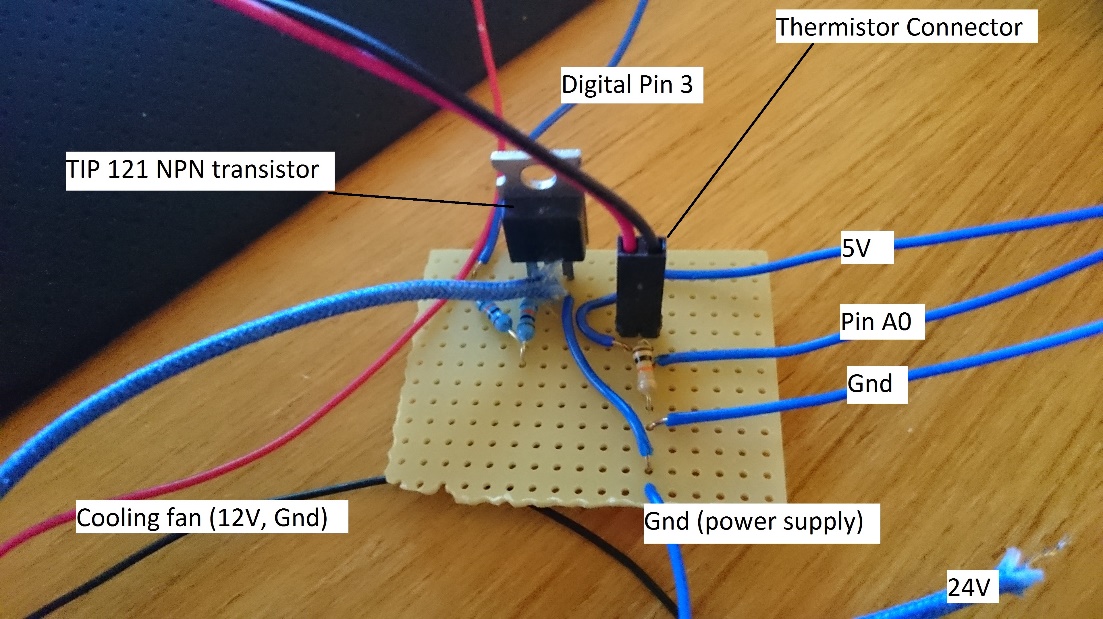
The photograph above shows the experiment between test runs. In the foreground the extruder can be seen filled with PVC and mounted to a stand, ready for weights to be applied on the syringe plunger, as well as the power supply and control circuitry. Note the Current reading on the 24V supply: no current is flowing, meaning the Arduino has not yet switched on the heating element. The 12V supply is providing power for the cooling fan, which is run continuously.
Extruder
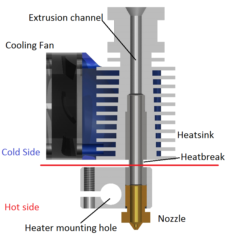
The extruder used for this experiment consisted of a syringe attached to an e3d v6 hotend with a 0.4mm nozzle, as pictured below. This particular hotend was modified by cutting a thread into the top of the heatsink and attaching a hose barb to connect a liquid feed.
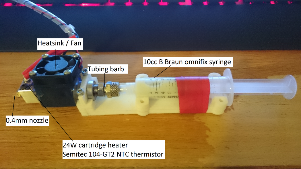
The entire apparatus is mounted on a 3D-printed bracket to hold all parts in aligment. The syringe containing the PVC, was connected to the hotend via a short length of 6mm silicone tubing. During the experiment, weights were applied to the plunger until cured PVC began to be extruded from the nozzle. The required pressure was then be calculated by knowing the internal diameter of the syringe and the force applied to it.
The e3d v6 hotend (pictured below) was chosen for this experiment because of its robust aluminium design and open-source community support, meaning that all required documentation was easily available. Furthermore, the aluminium body meant that it was quite easy to simply bore out and thread the extrusion channel to attach a hose fitting. Beginning with a commonly-used platform like the e3d series of hotends also allowed a reduced design complexity when integrating the nozzle into an existing 3D printer.
Temperature Control
In order to maintain the hotend at the desired temperature, a PID controller was implemented on an Arduino Mega 2560, using the following code:
#include <PID_v1.h>   			//PID library
#include <math.h>     			//Math library

double  Setpoint, Input, Output;  	//declare variables used in the code

double Thermistor(int RawADC){    	//declare the function that reads the temperature from the thermistor
  double temp;
  					//using the Steinhart-Hart equation
  temp= log(9600.0*((1024.0/RawADC-1))); //find the log of the resistance
  temp=1/(0.0008104849864+(0.0002115244184+(0.00000007098035250*temp*temp))*temp); 			//using the Steinhart-hart coefficients
  temp=temp-273.15; //convert absolute temperature into degrees celsius
  return temp;
}

//create a PID controller, defining input, output, setpoint, Kp, Ki and Kd, set to direct mode
PID tempPID(&Input, &Output, &Setpoint,21.28,2.37,47.76, DIRECT);

void setup() {
Serial.begin(9600);         //begin Serial communication
tempPID.SetMode(AUTOMATIC); //set PID to run automatically
Setpoint=0;                 //initialise setpoint to 0 (off)
}

void loop() {
  Input = Thermistor(analogRead(A0)); //PID input is the current temperature

  tempPID.Compute();                  //calculate the PID's output
  analogWrite(3, Output);             //write the output as PWM to one of the digital pins

Serial.print(Setpoint);              //serial outputs for datalogging
Serial.print(", ");
Serial.print(Input);
Serial.print(", ");
Serial.println(Output);
if(Serial.available() !=0){         //if there is a non-zero integer in the incoming stream
Setpoint=Serial.parseInt();         //set the setpoint to the integer
}
delay(250);                         //repeat 4 times per second
}
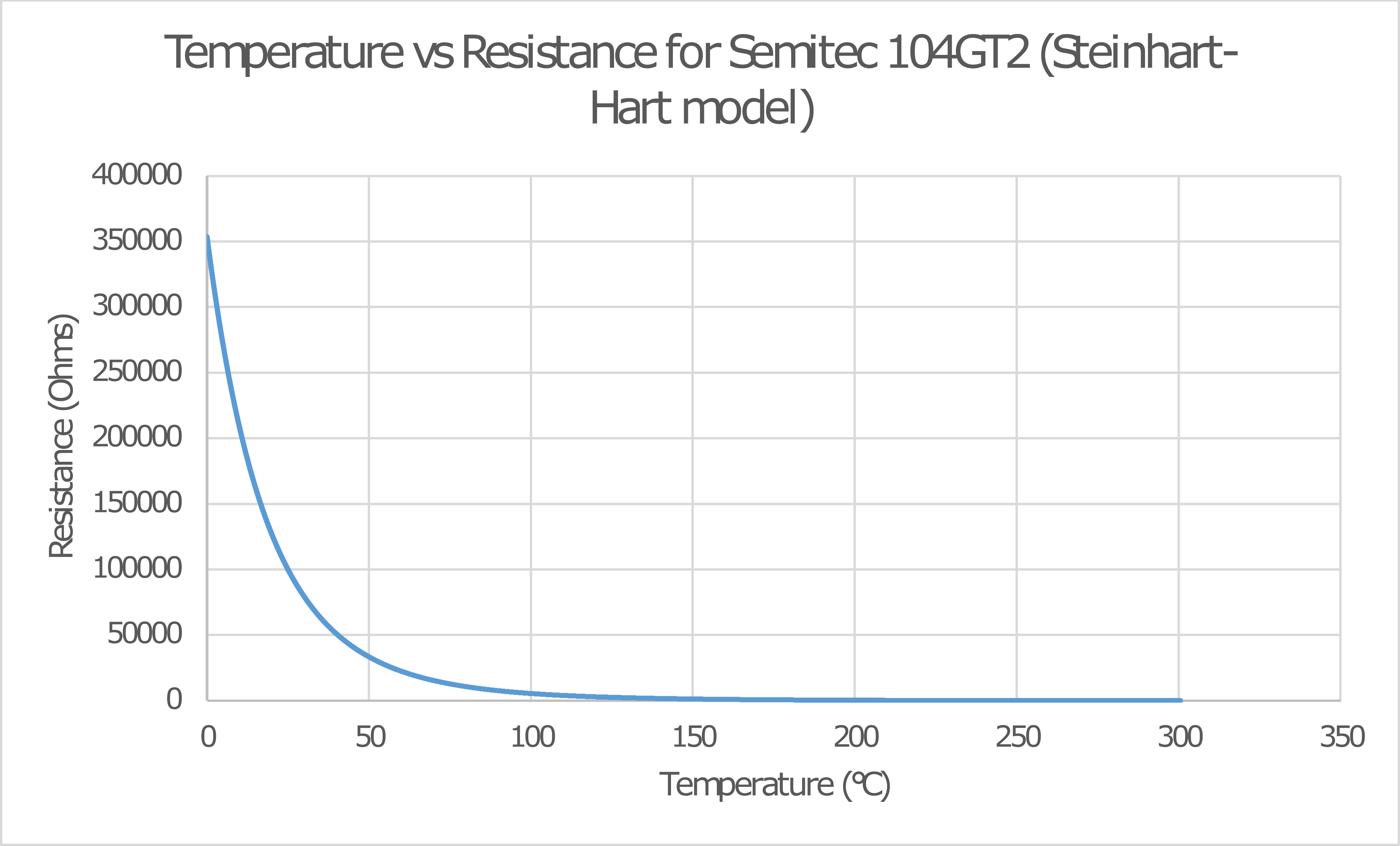
The Steinhart-Hart thermistor equation
The Steinhart-Hart equation referenced in the code comments is the following equation:
\[\frac{1}{T} = A+B *ln(R) + C[ln(R)]^3\]It models the behaviour of NTC (negative temperature coefficient) thermistors. The variables represent the following:
- T is the absolute temperature in Kelvin
- R is the resistance of the thermistor in Ohms
- A, B and C are coefficients individual to the resistor used. These can be acquired from the Thermistor’s documentation.
In this case, A, B and C were found by examining the manufacturer datasheet for the Semitec 104-GT2 thermistor found here. Considering the intended temperature range of the extruder would be between room temperature and approximately 250°C, the following resistance values were used:
| Data Point | Temperature (°C) | Resistance (Ω) |
|---|---|---|
| \(T_1\) | 0°C | 353.7 kΩ |
| \(T_2\) | 100°C | 5.556 kΩ |
| \(T_3\) | 200°C | 0.1740 kΩ |
Plugging these into the matrix calculation for A, B and C:
\[\begin{matrix} 1 & ln(353700) & (ln(353700))^3 \\ 1 & ln(5556) & (ln(5556))^3 \\ 1 & ln(174) & (ln(174))^3 \\ \end{matrix} * \begin{matrix} A \\ B \\ C \end{matrix} = \begin{matrix} \frac{1}{0+273.15} \\ \frac{1}{100+273.15} \\ \frac{1}{250+273.15} \end{matrix}\] \[\begin{matrix} A = 0.8104849864 * 10^{-3} \\ B = 2.115244184 * 10^{-4} \\ C = 0.7098035250 * 10^{-7} \\ \end{matrix}\]In other words, \(\frac{1}{T} = 0.8104849864 * 10^{-3} + 2.115244184 * 10^{-4} * ln(R) + 0.7098035250 * 10^{-7} [ln(R)]^3\)
In graph form, it looks like the following:
Circuitry
The hotend was powered using a 24V PSU borrowed from the electronic engineering department. The following circuit was used:
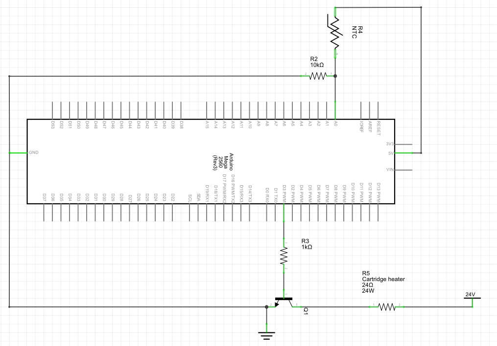
There are effectively two separate circuits in this schematic. The first is a voltage divider where R2 is a 10kΩ resistor and R4 is the NTC thermistor, allowing changes in the thermistor’s resistance to be measured as voltage changes by the Arduino. However, when measured with an Extech EX330 multimeter, the resistor was found to be closer to 9600Ω. To reduce errors due to this discrepancy, the 9600Ω resistance was used in the voltage divider calculation.
To calculate the output of the voltage divider, the following formula was used:
\[V_o = V_i (\frac{R_2 } { R_{Thermistor} +R_2 })\]Where \(R_2 = 9600\Omega\).
The second circuit contains the heater and a TIP 121 That allowed the Arduino to regulate the hotend with a PWM signal. The two circuits were assembled on a piece of protoboard as pictured below:
Procedure
The extruder was connected to the power supply and the control circuitry. After establishing contact to the Arduino via serial connection and beginning to log the data to the attached PC, the temperature of the extruder was set to the level desired for the test run. The air was manually purged from the extrusion channel by pressing down the plunger by hand until PVC began to be extruded from the nozzle, at which point no more force was exerted on the plunger. Once the flow of extruded PVC stopped, weights were added on top of the plunger in 2N increments until a steady stream of PVC could be observed being extruded from the nozzle of the extruder. At that point, the total force on the plunger was recorded.
Results
Syringe inner diameter was measured as 15.75mm.
\[Syringe Area=0.00194828 m^2\] \[Pressure = \frac{Force}{Area}\]| Temperature (°C) | Attempt 1 (N) | Attempt 2 (N) | Attempt 3 (N) | Mean (N) | Mean Pressure(Pa) |
|---|---|---|---|---|---|
| 210°C | 20N | 24N | 22N | 22.00N | 11,292.01 Pa |
| 200°C | 24N | 26N | 30N | 26.67N | 13,688.99 Pa |
| 190°C | 30N | 32N | 34N | 32.00N | 16,424.74 Pa |
| 180°C | 40N | 38N | 42N | 40.00N | 20,530.93 Pa |
Success!
We proved that liquid PVC can be cured and extruded from an e3d v6 hotend!