Adventures in 3D printing PVC - Part 3
07 Mar 2023Implementing my new knowledge in a 3D printer
First, I needed to know how to feed the extruder in a way that could be integrated in a 3D printer. At the time, I had a Kossel Mini from Think3DPrint3D running on a RAMPS 1.4 board, so ideally the feeding system could run on a regular stepper motor hooked up to the extruder motor driver on the RAMPS board.
In the end I settled on using a peristaltic pump.
To achieve a printing speed of 100mm/s (0.1 m/s) with a 0.4mm nozzle:
Cross-sectional are of the nozzle:
\(A=\frac{\pi d^2}{4}=\frac{\pi(0.4\cdot10^{-3})^2}{4}=1.2566\cdot10^{-7} m^2\) With a flow velocity of 0.1 m/s, this corresponds to a volumetric flow rate Q of: \(Q=A\cdot v=1.2566\cdot10^{-7} (0.1)=1.2566\cdot10^{-8} m^3/s\) Or about 0.75 mL per minute.
The flow rate of a peristaltic pump is calculated as follows:
\(Q=v_{tubing}\cdot n_{rollers}\cdot \omega\) Where $Q$ is in $mL\cdot min^{-1}$, $v_{tubing}$ is in mL, and $\omega$ is in RPM.
So, how much tubing is actually occluded by my pump? To do this I need to know the sizing of my tubing and the arc length.
\(L=\dfrac{\theta}{360} \cdot 2\pi r\) Where $L$ is the Length of occluded tubing, $\theta$ is the angle along which the tube is occluded and $r$ is the radius of the curve.
In my case, the tubing had an ID of 3.5mm, and is occluded along a 271° arc with a radius of 32.5mm, so the occluded length works out to be 0.153m.
Knowing the radius of the tubing, it’s easily to calculate the volume of the occluded tubing as 1.472mL.
So, to reach my desired flow, my pump must rotate at 0.171 RPM, which is totally doable, even for a motor that is highly reduced to increase the available torque.
“Steps per mm”
We don’t want to have to completely redo the flow math that the slicer and firmware have to do. Fortunately, the feed tube and regular filament have one thing in common, and that is the fact that both are cylindrical. Therefore we can theoretically just set the filament diameter in our slicer to be equal to the ID of our tubing.
However, we still need to figure out the actual steps per mm of our “filament” extruder. If we know the amount of liquid being pumped in one revolution of the pump, we can infer the “length” of “filament” being extruded as the height of a cylinder whose diameter is the ID of our tubing and of a volume equal to the amount of liquid metered by the pump in one rotation;
\[\frac{4v}{\pi d^2}=L\]Where $v$ is the volume of liquid pumped in one revolution, $d$ is the tubing ID, and $L$ is the length of “filament” being extruded in one motor revolution.
If we then divide the number of steps of the motor in one revolution, we can divide this number by the “filament length” to get our steps/mm value to start with.
However, for best results, it’s probably a good idea to only use this as a starting ballpark value and do some manual calibration.
Installing the modified hotend
In order to prepare the 3D printer for conversion to PVC printing and to integrate the PVC feed system into the 3D printer, it was necessary to swap out the 3D printer’s effector plate for a modified version. The hot end is secured to the effector plate using a locking clip which is then held in place by a set of 6xM3 bolts.
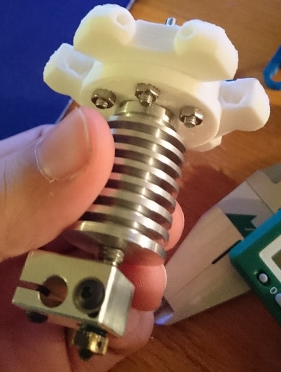
These bolts also secure a variety of other accessories to the 3d printer when the hot end is installed, such a supplemental cooling fan and a print bed levelling probe:
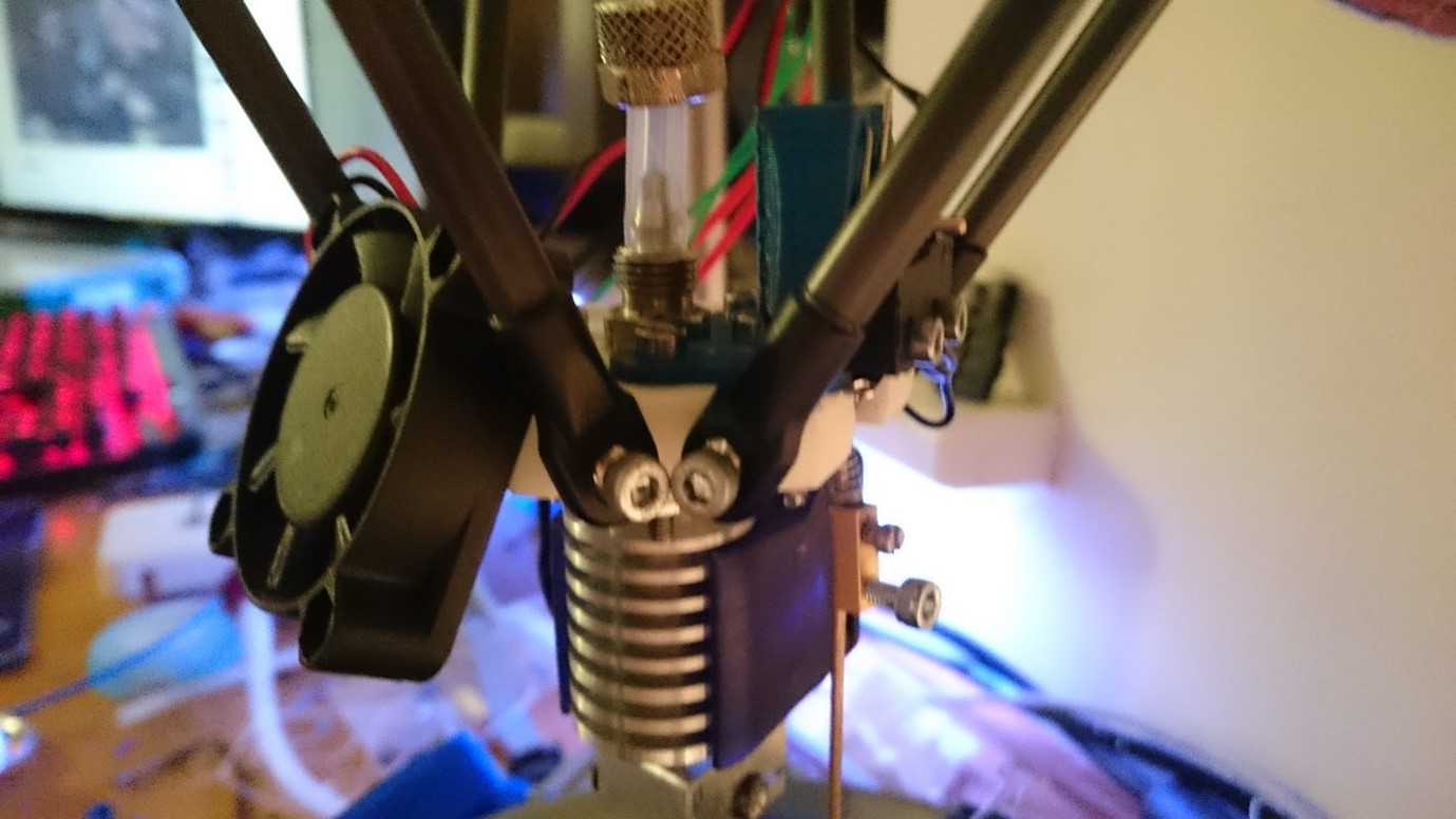
Once the hot end was installed, the silicone tubing was connected to the peristaltic pump. With all vital connections now made, it was possible to begin the first feed system test.
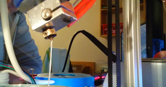
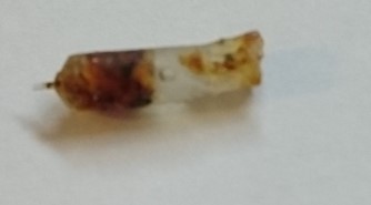
The first feed system test with the redesigned pump went exactly as was originally hoped; the pump was able to produce sufficient pressure to extrude the PVC from the nozzle of the hot end, and the material cured sufficiently on its way through the hot zone. It was, however observed that the extruded filament of PVC was filled with bubbles, see below:
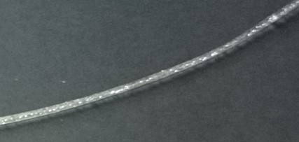
The PVC suspension tends to settle when stored for extended periods of time. In order to use the material, it must be gently shaken to restore a homogeneous mix to the suspension. As the suspension has a comparatively high viscosity, the entrapped air (particularly very small bubbles) does not readily escape out of the solution.
Bubbling is an undesirable condition for 3D printing, as air in the extrusion path can cause localised weaknesses in the material which reduce the printed part’s overall strength.
Additionally, it was observed that when the pump was made retract some pressure during printing (retractions are performed to prevent extruder “ooze”- the unintentional dragging of thin fibres of plastic behind the nozzle) the nozzle would temporarily lose pressure and would take too long to begin extruding material again. This condition is highly undesirable due to the fact that it causes underextrusion, a phenomenon caused by the deposition of too little plastic on the build surface. Underextrusion causes weak and porous prints which fail easily along the printing planes in the finished model.
Unfortunately, this condition proved very difficult to solve, as it was caused by backlash in the gearing. All gears require just enough space to clear the non-meshing teeth. This means that engaged teeth have a small amount of play – meaning that the two gears can move relative to each other without transferring the right amount of motion. This mechanical loss was aggravated by the fact that FDM 3D printers only possess limited precision.
Finally, it was observed that, if left idle for too long at 210°C or higher, the nozzle of the printer would become clogged. On disassembly, it was found that the nozzle had clogged due to the PVC degrading inside the nozzle, causing a blackened plug to form in the extrusion path.
Corrective actions taken in response to results from feed system testing
Based on the information gathered during the initial round of feed system testing, three actions were taken, outlined below.
1. Nozzle clog
To solve this issue, both software and hardware solutions were implemented. Firstly, the printer nozzle was upgraded from a 0.4mm aperture brass nozzle to a 0.8mm stainless steel nozzle. Smaller nozzles, such as the 0.4mm nozzle being used cause higher backpressures in the feed system, and don’t allow any “idle leakage” from the extruder – small amounts of plastic forced from the nozzle due to thermal expansion. This idle leakage reduces the build-up of overheated PVC in the nozzle.
Secondly, it is possible to reduce the amount of hot time by modifying the G-code so that the hot end only heats up immediately before beginning to print using the following line of G-code:
M109 S[first_layer_temperature]
Next, the printer can be told to deactivate the cartridge heater immediately after completing a print using the command:
M104 S0
In practice, these two changes have eliminated any further occurrences of nozzle clogging due to degraded PVC.
2. Replacement of the peristaltic pump
As it was not possible to produce the same pump design with no backlash, it was decided to replace the peristaltic pump entirely with a directly-driven (zero backlash) peristaltic pump.
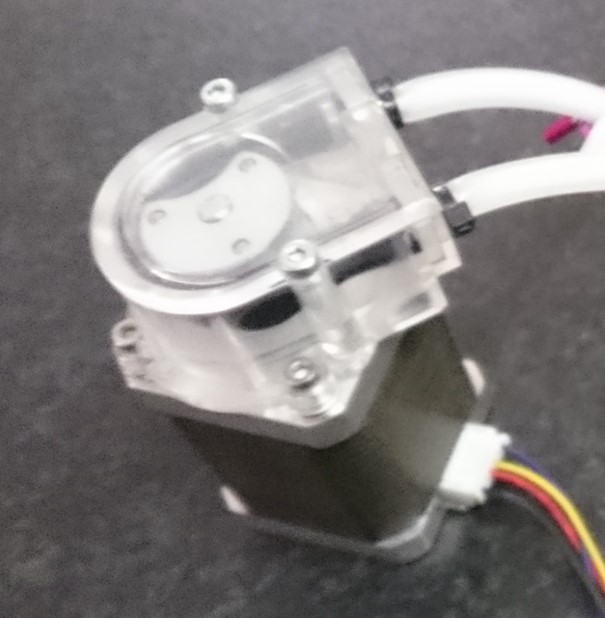
The purchased pump, with its direct-drive design, works perfectly when combined with the 65Ncm NEMA 17 motor, and has prevented any further occurrences of retraction/backlash-related underextrusion.
3. Bubble reduction / degassing
In order to address the bubble formation problem, it was decided to create a theoretical design for a degassing unit attached to the PVC reservoir. Before initiating a print, the reservoir would be reduced to about 0.5 Bar absolute pressure. This low vacuum would be maintained for one minute, after which the unit returns the reservoir to ambient pressure. To remove the maximum amount of bubbles from the PVC suspension, the system would pulse the vacuum, reducing the chamber pressure and returning to ambient repeatedly.
In practice, the PVC suspension was simply allowed to sit undisturbed for a minimum of one hour before initiating a print, giving the air plenty of time to bubble out.
Calibration of the new pump
The newly-bought pump had to be calibrated to allow the printer to use the extruder correctly. Unfortunately, exact data of tube diameters, etc. was not available from the manufacturer, so the steps/mm calibration had to be performed empirically.
To calibrate the pump through physical measurements, rather than by calculating the correct value, a way of controlling the motor had to be come up with. To this end, an Arduino mega 2560 was used in conjunction with a discarded Pololu A4988 stepper motor driver, in a configuration similar to the one pictured below:
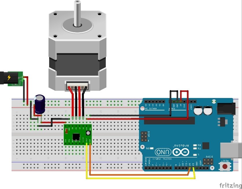
For the 12V supply, a common mains-fed “power brick” was used, which provided power to both the Arduino (via the Vin pin) as well as the stepper driver through the Vmot pin.
Additionally, two buttons were added to send the motor 5000 steps in one direction or 5000 steps in the opposite direction.
The following Arduino Code was used:
#include<a4988.h> //A4988 stepper driver library
//define the which pins on the A4988 are connected to what
#define MS1PIN 8
#define MS2PIN 9
#define MS3PIN 10
#define DIRPIN 4
#define STEPPIN 5
#define ENABLEPIN 6
#define MOTOR_STEPS 200
//initiate an instance of the A4988 library object and call it "myA4988"
a4988 myA4988(MOTOR_STEPS, MS1PIN, MS2PIN, MS3PIN, DIRPIN, ENABLEPIN, STEPPIN);
void setup() {
  //do not enable the motor on boot
  myA4988.enable(0);
  //set the stepper driver to 1/16th stepping mode
  myA4988.setStepMode(16);
  //sets the microsecond delay betweeen steps
  myA4988.setDelay(800);
}
void loop() {
  //if button A is pressed, send 5000 steps in one direction
  if(digitalRead(14) == HIGH){
    myA4988.setDirection(0);
    myA4988.step(5000);
  }
  //if button B is pressed, send 5000 steps on the other direction
  if(digitalRead(15) == HIGH){
    myA4988.setDirection(1);
    myA4988.step(5000);
  }
}
By filling the tube with water and running the pump, it was possible to measure the distance the water was moved through the tubing, making it possible to calculate back the number of steps per mm.
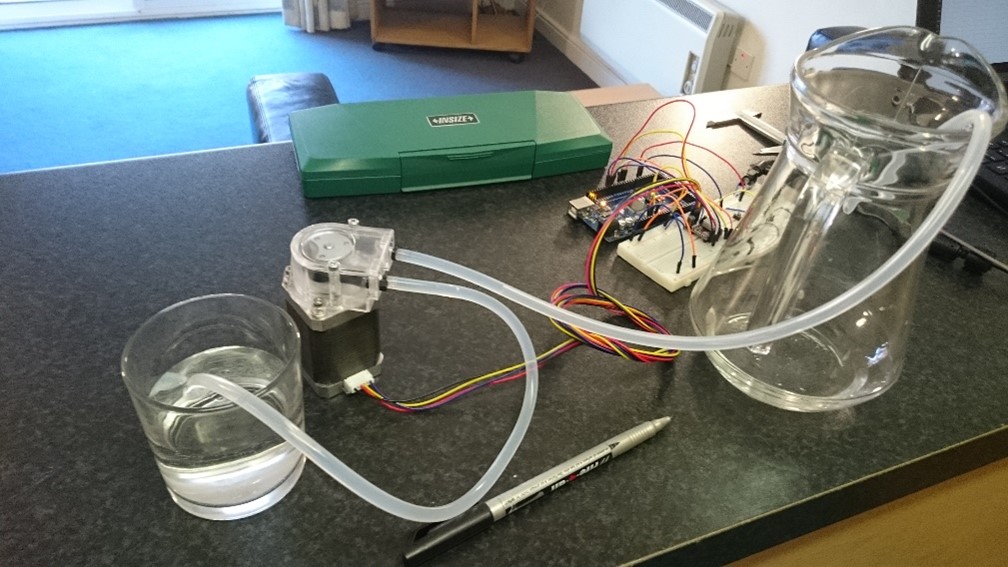
The meniscus of the water in the tube was marked off using a permanent marker. The pump was then set to run 5000 steps, and the displacement of the meniscus inside the tube was recorded. Ten runs were performed and an average value for steps per mm was calculated.
| Run | Steps | distance | steps/mm |
|---|---|---|---|
| 1 | 5000 | 64 | 78.1250 |
| 2 | 5000 | 64.06 | 78.0518 |
| 3 | 5000 | 64.46 | 77.5675 |
| 4 | 5000 | 64.12 | 77.9788 |
| 5 | 5000 | 64.6 | 77.3994 |
| 6 | 5000 | 63.98 | 78.1494 |
| 7 | 5000 | 64.63 | 77.3635 |
| 8 | 5000 | 63.94 | 78.1983 |
| 9 | 5000 | 63.81 | 78.3576 |
| 10 | 5000 | 64.13 | 77.9666 |
| avg | 77.9158 | ||
| stdev | 0.3304 |